White button mushroom
is a temperate mushroom requiring cooler climate for its growth. It is an indoor
crop and is an ideal tool in converting agricultural wastes in to proteinaceous
food. In early days its cultivation was mainly confined to the hills. In the
eighties growers realized the potential of this crop and started its cultivation
in the northern plains in the winter when the climate was suitable for its
growth. Many entrepreneurs in the plains further ventured and started its
cultivation round the year by employing artificial cooling facilities (chilling
stations). Today its cultivation is done through out the country Some are doing
it seasonally while many of them have preferred to go for round the year
cultivation. Today India boasts of having world�s biggest farm, the Agro Dutch
Foods Ltd, Lalru Punjab and many more environment controlled units exit in
different parts of the country cultivating this mushroom round the year.
Mushroom being an
indoor crop does not require arable land, except for some nonagricultural land
to build the infrastructure for preparation of substrate, raising of crop
preparation of spawn and postharvest handling. As mentioned above this mushroom
is grown seasonally and in environment controlled cropping houses and both
require building of basic infrastructure. Seasonal growing is done for 3-4
months when outside temperatures are favourable for the crop, i.e., during
winter months in N.W. plains and from September to April in the hills .
Seasonal cultivators of
this mushroom are using traditional methods of its cultivation and are mainly
cultivating this mushroom in the thatched structures employing long method of
composting. They usually take single crop in the entire season and are
harvesting 12-15 kg mushrooms/ 100 kg compost. Environment controlled units are
cultivating this mushroom round the year by having suitable infrastructure at
their disposal which includes a modern composting yard having bulk
pasteurization facilities. Of late few of them have shifted to indoor composting
while new upcoming units have chosen to produce their compost entirely by indoor
method. Besides these facilities they are having insulated cropping rooms and
other ancillary structures required for mushroom cultivation. Few of the bigger
units are having their own spawn lab and processing unit as well. An
entrepreneur can start mushroom cultivation modestly using seasonal growing
houses and after gaining sufficient experience can shift to round the year
cultivation employing suitable climate control facilities. Suitable
infrastructure including different machineries are required at the farm to carry
out different operations to govern the whole process of cultivation in such a
fashion so that one gets optimum returns from his farm in this competitive
environment. The one who designs the farm in most scientific manner looking to
the need of the crop and easy accessibility to the different infrastructure for
their operation convenience in less space, utilizing less money will gain
handsome returns in the years to come. Present chapter would deal in detail the
infrastructure and machineries required for the seasonal and environment
controlled units.
A. Selection of Site and Pre-Requisites
Before selection of site,
the following points have to be taken into consideration for greater operational
efficiency and cost effective production of mushrooms at the farm:
1. Chosen site should
preferably be away from the municipal limits and entrepreneur should purchase
sufficient land in one go looking to the future expansion.
2. The site should be
serviced by a motorable road, or nearer to a road head to reduce costs on
transportation of raw materials to the farm/finished product to the market.
3. Plentiful availability
of water at the site either through a perennial source or should have sufficient
underground water.
4. Easy availability of
raw materials especially straw and poultry manure around the chosen site at
cheaper rates in the area.
5. Availability of cheap
labour in abundance.
6. Uninterrupted proper
power supply at the chosen site.
7. Nearness to the market for the
proper disposal of the produce.
B. Components of a Mushroom
Farm
For round
the year cultivation of this mushroom employing environment-controlled
conditions a medium size plant would require under mentioned components.
1. Spawn
unit
For
producing in-house spawn for self requirement and for sale to other units. This
will have under mentioned major components.
a
Cooking/autoclaving room: For
boiling the grains and sterilization of the bottles/pp bags.
b
Inoculation room: For
inoculation of the sterilized bottles/ pp bags
c
Incubation room: For
incubating the inoculated bottles. Insulated and provided with AC.
d Cold
Store: For
storage of prepared spawn for its further disposal
Besides
above some ancillary structures like office, small lab space, delivery area,
etc. may also be required.
Machineries
required: Air conditioners, Laminar flow system, Autoclaves, BOD incubators,
Boiler, Boling cattles, Refrigerators, racks, pH meter, gas stoves, etc.
2.
Composting unit
This will have under
mentioned main components for production of compost
a Pre
wetting area: For
dumping of raw materials and their pre wetting (uncovered).
b
Composting yard: For
making piles out of the wetted materials (covered)
c Phase-I
bunker: For
phase -I composting (incase indoor composting is employed).
d Phase
-II tunnels: For
performing pasteurization and conditioning of the compost.
e Casing
soil chambers: For
pasteurization of the casing soil.
f Spawning
area: For
spawning of the prepared compost
Besides
above certain ancillary rooms like boiler room, underground service room, store
room, workers room, etc. would also be required Machineries viz., boiler,
blowers, air handling units, gratings, digital thermometers, compost retaining
boards, ventilation system for phase -I bunkers would be required by a medium
size farm (up to 200 TPA). Large farm besides above may require a front end
loader (Bobcat) and other compost handling equipments including turner, filling
line, etc.
3.
Cropping unit
A cropping
unit will have series of insulted rooms of designated size depending upon the
production targets. Besides rooms there will be AC/ compressor room, packing
room, central corridor housing air handling units and pipelines.
Machineries
required: Insulted doors, central chilling station (ammonia or freon based), air
handling units, computer based controllers (optional), racks, and trolleys,
harvesting trays, etc. would also be required. For continuous electric supply to
phase-I, phase- II tunnels and cropping rooms, generators of desired capacity
would also be needed.
4. Post
harvest handling unit
It will
have under mentioned components:
a
Pre-cooling chamber (cold room): For
storing the mushrooms before canning
b
Canning hall: For
housing the canning line for processing
c
Laboratory: For
quality control of processing
d
Store: For
housing the processed can
e
Office: For
sitting of the staff
f
Machinery required: Canning
line of desired capacity
5. General
Layout/Location of various Units
The layout
is so planned that all the infrastructures required to be built are accommodated
in least possible land without over looking mushroom cultivation requirements.
The general layout of a mushroom farm has to be carefully planned after
selection of the site, keeping in view the several factors including
accessibility of road to the composting yard as raw materials are to be dumped
here for their processing to the compost. Wind direction is also kept in mind
for choosing the location of the composting facilities. During most of the time
of the year wind should flow from cropping area to the compost yard and not vice
versa. Phase-I bunkers are constructed in line nearer to the phase -II tunnels
for their operational convenience and also to avoid heat losses. The bulk
chambers are built nearer to the phase-I bunkers. Both these structures are
preferably built away form the road at the distant end of the yard so that the
distant end of the phase -II tunnels opens nearer to cropping rooms and away
from composting yard (Fig. 8.1). The cropping rooms are built away from
composting area for reasons of cleanliness and avoiding contamination by pests
and pathogens. The casing pasteurization chamber is built nearer to the
composting yard or within the composting yard with small platform for preparing
the casing soil (Fig. 8.1). Enough space for future expansion of composting
yard, construction of more phase-I & II chambers and growing rooms should be
left vacant for planned development of a mushroom farm in a phased manner. Spawn
unit is built far away from the composting yard and nearer to the cropping area.
Processing unit can be a separate entity or can also be built within the
building housing cropping rooms.
The
foundation of the buildings is dug on the firm ground. The underground water
pipes, electrical cables and sewers are laid well before the actual construction
starts. The entire site area should preferably be fenced or brick walled for
security reasons. In areas where land is scarce, double story cropping houses
can be built to economize on space. The cropping rooms are generally built in
double rows with a path/gully in between for various operations and services.
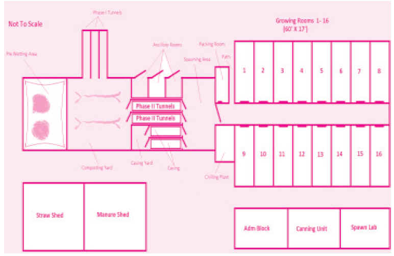
Fig 1. General
layout of the farm
a.
Composting unit
The
components of composting unit will depend upon the method of compost production
chosen. If one is going for indoor compost production, in such a case
requirement of composting yard will be greatly reduced and it will be 1/3 of the
normal yard required when one has chosen SMC. Now a days trend is for indoor
compost production due to environment legislation. In such a case a small pre
wetting area, and small covered composting yard would be required with minimum
of two-phase-I bunkers and one phase-II tunnel. Size of all these structures
would depend upon the production targets of the unit and size and numbers of the
tunnels.
b.
Prewetting area (PWA) (lagoon)
This area
is constructed nearer to the road. It is a simple cemented structure having a
saucer like depression in the center so that it looks like a lagoon and water
remain collected during the prewetting of the compost ingredients (Fig. 8.1).
Center of the lagoon should be around 1 ft deep. Excess water of the lagoon is
collected in a goody pit built specially for the purpose at a convenient place
around PWA for its reuse. Floor of the PWA should be such that it can withstand
the load of the front-end loader while performing the wetting operations. It is
usually not covered and is open to the sky. PWA terminates in the composting
yard. Water connection with 2"-3" dia. pipe should be available in PWA
permanently with additional portable hosepipe for use during pre-wetting. One
dewatering pump with a hose should be installed in the goody pit to pump out the
run-off water for its reuse during pre-wetting. Water in the goody pit may be
aerated continously to avoid foul smell.
c.
Composting yard
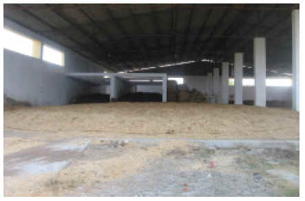
Fig.
2 Composting
yard including Phase-I bunker
The
composting yard (Fig.2) is required for phase-I of composting. It is a
prerequisite when one is going in for short method. The composting yard should
necessarily be a covered shed with 2-3 ft sidewalls on the two sides (length
wise) where rain will not interfere in the normal process of composting. The
foundation of the composting yard should be laid on a firm ground and it should
necessarily be reinforced if mechanization of the composting yard has to be done
as it has to withstand the load of heavy machines. The floor is given a run-off
of 1 cm per running meter away from the bulk chamber and towards the goody pit
end.
The roof of the
outdoor composting platform is built on tresses or RCC pillars 16 ft high with a
GI or any other suitable roofing. The covered The composting yard should be big
enough to hold maximum compost stacks for phase-I of composting. When adopting
indoor compost production wetted ingredients are just made up into a heap for
3-4 days and do not require rick formation in such a case a small platform can
suffice the purpose.
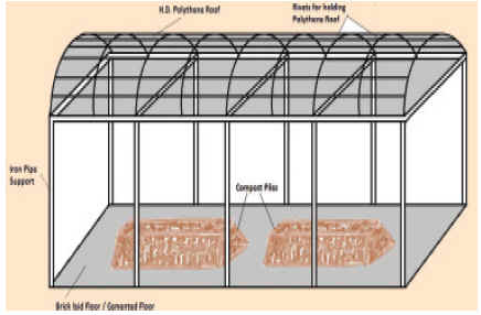
Fig 3. Low
cost composting yard
However, a
large composting yard would be required if SMC is adopted. On an average
one ton compost occupies about one meter length of the composting yard, with an
extra space of 2-3 m left on each side for turning with machines. Two bulk
chambers will have a platform with 10-15 m width. For two bulk chambers of 25
tons capacity each, a composting yard of 25 m x 13 m should be good enough to
concurrently run phase-I operation at a time for both the chambers. A drain
should run on the two sides of the platform to facilitate periodic cleaning. A
few three phase 15 amp. power connection should also be provided at the
composting yard for operating machines like hopper regulator, compost turner,
filling lines, etc. The yard should be well lighted with tube lights and strong
searchlights to facilitate round the clock operations at the composting yard
An
overhead water tank is necessary, particularly where water is scarce, to store
water for timely operations. The floor of the composting yard for long method of
composting should be simply cemented/brick layered with a low cost roofing of
high-density polythene fixed on iron tubular structure or it can also have
thatched roof (Fig. 3). In practice (90%) of the farms cultivating this mushroom
seasonally are preparing their compost in the open fields and do not have any
specially built composting yard built for the purpose. However, such growers are
facing lot of disease and pest problems. We recommend that the compost by long
method by seasonal growers should at least be prepared on a cemented platform-
let it be open to the sky.
d. Phase-I tunnels
(bunkers)
This
facility is required when indoor composting is employed at the farm. These are
specially built non-insulated tunnels having full width opening at the front
(Fig. 4). Dimension of the bunkers would depend upon the output of the compost
required. Generally the bunkers are 1.5 times more the size of the phase -II
tunnels. It has a plenum (ventilation duct) constructed below the actual floor.
A perforated concrete floor having around 1 cm openings at a distance of 1ft
each to the entire floor area is constructed above the plenum or it has simple
RCC /steel gratings having 20% opening to the entire surface area of the tunnel
(Fig. 5) which is serviced by a centrifugal fan having 1/4th the capacity of
phase two blower which means that a ventilator having air displacement of 50 m3
per hour ton of compost at 50 mm WG water pressure would suffice the purpose. A
plenum floor involves pressurizing the entire airspace beneath the concrete
floor, allowing the air to move up into the substrate through the holes or
through series of slates.
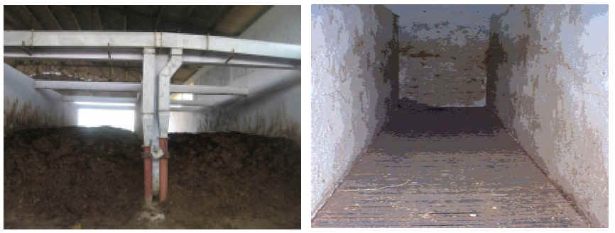
Fig. 4. Bunker
Fig. 5. Gratings
over the plenum
Alternatively
the bunkers have no plenum and several pipes (5-15 cm dia) are buried in the
floor along the full length of the bunkers having small holes (5-10 mm dia) at a
distance of 15 to 30 cm each (Fig. 6). These pipes converge into a manifold,
which in turn is connected to a high-speed blower fan (around 1000 Pascal). A
timer is usually attached to the blower, which pulsates the air in the bunker
periodically as per the setting of the timer. A minimum of 2 such phase-I
tunnels (bunkers) are required.
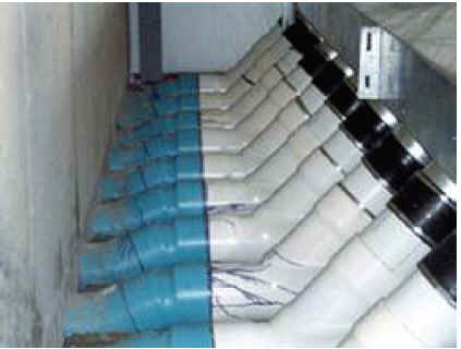
Fig. 6. Bunker with
aerated pipes
A bunker for 20-25 ton compost output at the time of
spawning may have thedimensions 45 x 10 x 8 with 9 pipes of 2.5 m dia. at
distance of 1 ft. (6� from the wall). To equalise the pressure either the pore
size may be increased or distance between the holes may be gradually decreased
from 1.5 ft. to 9�. These 9 pipes are linked to a bigger pipe of about 6�
dia. which inturn is linked to a centrifugal blower.
i. Pasteurization facility
A modern farm employing either indoor method or SMC essentially
requires this facility. The bulk pasteurization chamber is principally used for
phase-II of composting for pasteurization and conditioning of the compost. For
this purpose, an insulated chamber is built with facility for steam injection
and controlled recirculation and fresh air entry in the tunnel through a blower.
The insulated chamber is built with purpose of cutting off the external
environment and simulating a desired environment inside for controlled
fermentation of the compost ingredients.
In Bulk pasteurization chamber compost is handled in bulk inside
the tunnel or chamber and hence the name bulk chamber. The compost after phase-I
is filled into specially built chamber, which is properly insulated and provided
with steam connection and air blowing system for re-circulation. The compost is
filled in the chamber on top of its grated floor built over the plenum. The
plenum has an air circulation duct used during pasteurization/conditioning (Fig.
7).
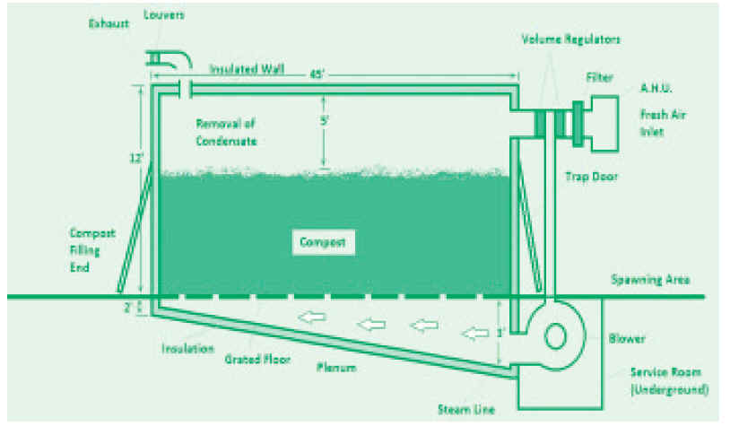
Fig. 7. Cross-section of the bulk chamber
(45� x 9� x 13�)
The bulk chamber should be constructed on one end, (away from
road) of the composting platform. One end of the bulk chamber should open into
the platform and the distant end in the clean spawning area. The foundation of
the bulk chamber should be dug on a firm base ground. The floor must be laid
with a good run-off provided with a drain to facilitate cleaning. It is
pertinent here to note that this floor is given a slope towards the service area
end (blower end). A large tunnel will be around 90 cm deep towards the blower
end while it will be around 15 cm deep towards other end (filling end).
Floor should be properly insulated with thermocol/glass-wool 5
cm thick (15 kg/m2 density). The insulation is covered with isolating membrane
of PVC sheeting followed by 5 cm cement floor and finally the finish. Such floor
is constructed for both cropping room and the chamber. The walls should be
9" thick (one brick lengthwise) built over the concrete foundation. The
length and breadth of the bulk chamber will vary, depending upon the amount of
compost to be treated in the chamber, with the height of 13 ft, the roof is made
of 4" thick RCC. The walls, ceiling and the floor below the plenum are
insulated with 5 cm thick insulating material (15 kg/m2 density) necessary for
effective insulating effect during pasteurization and conditioning of the
compost. Required K value of the insulating material should be around 0.5-0.6
kcal/ m2/h. Air leakage in bulk chamber must be prevented at any cost. The bulk
chamber has two floors one is real insulated floor while another false or grated
floor, which is laid above the actual floor or plenum over the ventilation duct.
The grated floor must allow the air to pass through, for which approximately
25-30% of the floor area is left in the form of gaps for ventilation/circulation
of air and steam. The plenum is divided with a perforated brick wall (one or
two) in the centre for supporting the grated floor. The gratings can be made of
wood (painted with bituminous paint), coated iron strips mounted on angle iron
frame or with concrete beams. Alternatively a concrete floor can be poured over
the plenum as in case of phase -I tunnels having openings. If nylon nets are to
be used for mechanical filling and emptying, then cemented grated floor with
appropriate RCC strength is built specially for the purpose. The doors of the
bulk chamber are made of angle iron or wooden frame with 2-3" insulation in
the middle and covered on both side with aluminum sheets, else they can also be
made up of puff panels. The chamber will have two exhaust vents, one for
recirculation exit and the other for exhaust of gases on introduction of fresh
air via dampers.
The steam line is also connected at the entry point of the
blower. The walls and ceiling can be damp proofed by coating bituminous paint on
inside over the cemented surface, which will also serve as an effective vapour
barrier. The grated floor inside and the work floor outside should be of the
same height for operational convenience especially when tunnel has to be filled
mechanically.
Two types of tunnels (bulk chambers) are in use, two door bulk
chambers and single door bulk chambers. In the single door bulk chamber, the
same door is used for filling and emptying and the other end is utilized for
fixing installations (blower, etc.). In double door bulk chamber, one door is
used for filling (which opens into the composting yard) and the other for
emptying (opening into the sterile spawning area).
The bulk chamber can be filled/emptied manually or by conveyer
belts. The uses of machines for filling/emptying are labour saving, time saving
and ensure homogenous filling as well as maintenance of absolute cleanliness
during operations. For mechanical emptying two nylon nets are used, one fixed
over the RCC grated floor (gliding net) and the other moving over the
lower net (pulling net). The compost when brought out is fed into the
spawn-dosing machine where requisite amount of spawn is mixed with the compost
and the seeded compost is then poured into clean polythene bags for transport to
the growing rooms.
The dimension of the tunnel for producing 20-25 ton of compost
are 36� x 9� x 13�. One may replace the plenum with plastic pipes fitted
with spigots (Fig..8). The centrifugal fan can be placed at the bottom as well
as on the roof (Fig. 9) depending upon the space and design.
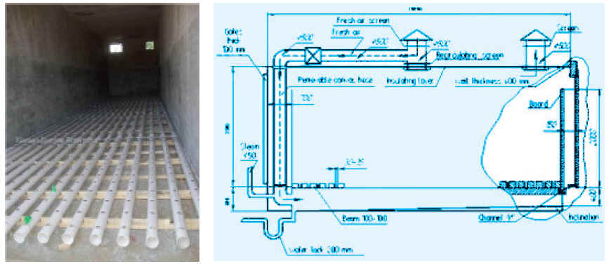
Fig. 8. Plastic
pipes ready for spigot
fitting
Fig. 9. Line
drawing of Phase-II tunnel for 20-22 ton compost output
(Source:
http://www.21food.com/)
(Source: http://www.agaricus.ru
)
e. Air handling units of the tunnel (AHU)
For effective pasteurization and conditioning of the compost in
the tunnel specific requirements of air and ventilation are to be met, which are
generally met by providing/installing AHU in the tunnels (Fig. 10). Effective
pasteurization and conditioning is attained when 150-200 m3 air per ton of compost per hour is
blown through the compost mass. For this purpose high speed centrifugal fan is chosen and
is placed on the slope end of the ventilation duct in the underground service area.
Compost is spread over the plenum on the grated floor in about 2-2.2 meter thick layers.
Nylon nets are generally placed under the compost if mechanization is necessary. These
together give a resistance of around 60-65 mm WG during pasteurization taking together the
resistance of the air ducts, the in and out openings, the perforated floor, etc. the
static pressure of the blower fan should be around 100 mm WG at 150-200 m3 air per ton of
compost per hour. Blower fan must be well protected internally and should be made up of
sheet steel. Aluminum is ideal for air ducts and should at least be 2 mm thick and there
should not be any leakage in the duct system. Ducts are generally insulated with glass
wool or any other suitable material. Fresh air is regularly required in the tunnels and
since this air is drawn from the open atmosphere, chances of fungal spore�s contamination are
likely and hence the incoming air in the ventilation duct should be filtered and
should pass through 2 mm fungal spore filters. The pre filters and filters should be
washed at regular intervals. The inlet and exhaust openings must be fitted with a flap valve,
which opens only when positive pressure is created inside the tunnel. The
dimensions of inlet and exhaust openings should be the same.
Since, India is a tropical country where temperature during
summer months goes above 45�C. Cooling of compost for spawning during this period
becomes difficult by simple introduction of fresh air. Special cooling arrangements
are therefore required to be made in the AHU of the tunnel for this purpose. A ten ton
capacity cooling equipment or cooling coils from the central chilling plant is installed at
the top of the AHU or such coils can be fitted in the blower section of the AHU. This arrangement
is very effective in cooling of the compost in tropical areas during summer months.
Installation of such facilities however requires heavy investment. Compost during these months
can satisfactorily be cooled during nights when the temperature is low.
f. Casing pasteurization chamber
Casing pasteurization chamber is just a mini bulk chamber. It
has all the necessary components as required for the tunnel. Only difference is that
the plenum is not having any slope and capacity of the blower for proper steam injection
and its uniform distribution inside the casing mass is around 1/4 the capacity of the tunnel
(Fig. 11). The size of the chamber will depend upon the size of the compost chamber and the
size of the growing rooms. One chamber load should provide casing for one compost
lot from each tunnel.
The casing inside the chamber can be treated in the bulk and in
such case it is filled up to the height of 90 cm only as against the tunnel where compost is
filled upto the height of 2-2.2 meters. Else casing after wetting is filled into the
perforated wooden/aluminum trays which are stacked one over the other inside the chamber and
steam treated at 65�C for 6-8 hours. This chamber can be built near to the composting yard
or within the composting yard with a separate casing mixing platform.
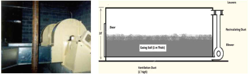
Fig. 10. Tunnel
with air handling
unit
Fig. 11. Casing
pasteurization chamber
g. Spawn unit
The layout plan of a spawn laboratory is given in Fig. 12. A
total built in area of 60� x 30� x 12� should be good enough to house the entire spawn
unit. This area will be divided into different work areas like boiling/autoclaving room,
inoculation room, incubation room (insulated and with AC), cold room (heavily insulated with
chilling facilities), store, office and delivery area.
h. Cropping unit
Since mushrooms are grown indoors under simulated environment
specially created for mushroom growth, the cropping rooms are required to be built
specially for the purpose Two types of cropping rooms are built suiting to particular
requirement - those required for seasonal growing and those for environment controlled growing round the year
(Fig. 13).
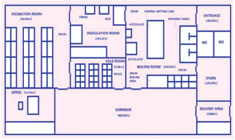
Fig. 12. Layout
of plant of a spawn lab
Seasonal cropping rooms:
Seasonal
cropping rooms are simple rooms with modifications for maintaining various growth parameters. These
cropping rooms will have a cemented floor, cemented walls, cemented ceiling or a
false ceiling with arrangement for forced air circulation inside. The seasonal
cropping rooms are built of simple brick walls with roof made of asbestos sheets and a false
ceiling. The room is more or less made air tight to make the air handling system work
effectively for obtaining necessary air changes during growing. No insulation is required
for seasonal growing rooms, as it will not allow heat dissipation from the room
efficiently. These simple rooms are used for seasonal mushroom growing, coinciding various
phases of growth with prevailing outside temperatures. No energy is generally used for
heating/cooling of the rooms under seasonal growing conditions. However few units in
plains have installed heavy-duty coolers to bring down the temperature in summer
conditions. The cropping rooms for seasonal growing can also be made with a thatched roof
and a false polythene ceiling. The door is installed on one end and the exhaust vents
on the opposite end of the door (Fig. 14). The mushrooms are grown on beds made out of
bamboo sticks and sarkanda stems (a plant abundantly growing as a weed in North
western plains of India). These growing rooms can also be built as low cost structure,
steel pipe frame with highdensity polythene covering from outside. The real low cost growing
houses built in rural areas are made of walls, roof and door of sarkanda.
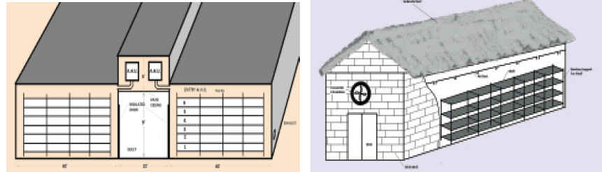
Fig .13. Cropping
section of the mushroom
unit
Fig. 14. Cropping
section of the mushroom unit
The mushroom houses made with bamboo frame and synthetic fiber
cloth material, both inside and outside, with paddy straw insulation in between
has also given good results under hill conditions for seasonal growing.
i
. Environment controlled cropping rooms
The environment controlled cropping rooms are built like
hermetically sealed chambers where the air movement is controlled either manually or
semi automatically with mechanical control systems. These cropping rooms are
appropriately insulated and the dimensions of a cropping room are determined by the
amount of compost to be filled into the room. Rooms with greater length and narrower
width gives better results as far as air handling inside the room is concerned. A cropping
room, with a capacity to take compost from one bulk chamber, is considered advantageous as one
bulk chamber load can straightaway be filled into one cropping room. Further,
cropping cycles to be taken will determine the numbers of growing rooms in the unit.
Now a days 60 days cropping cycle is generally taken and in this manner a minimum
of six crops are taken / room in a year. In such conditions a minimum of 12 rooms are
required to have constant supply of mushrooms from the unit round the year. In this case
every room is filled with the spawned compost every after 5 days. Both bulk chamber and
cropping rooms of 20-25 tons compost capacity are considered to be operationally
efficient, as the filling/emptying operation and spawning can conveniently be done in one
day when machines are not to be used. However, bigger units may have the growing
rooms handling compost to the tune of 60 tons or more. Growing rooms are such designed
that maximum compost can be accommodated in least possible area without over
looking to the mushroom growing requirements. To give an example a room size of
60 x 17x 13 ft can easily accommodate 20-25 tons of compost when cultivation is
done in shelves or bags. The foundation of growing rooms should be laid on dry and firm
ground. The floor is laid as explained for bulk chamber. The walls will be made of
one brick thickness (9"thickness) and ceiling made of 4" thick RCC. The growing
rooms will have a single insulated door and 2 vents for exhaust on the back wall 2-3 ft
above ground level. One opening is provided on top of the door for entry of the Air
Handling Unit (AHU) delivery duct or for fresh air intake inside the room through AHU. The walls,
ceiling and floor should be insulated with 5 cm thick insulating material. The room should
be made airtight and all leaks closed to prevent ingress of heat from outside. The
cooling, heating and forced air circulation in the growing room is done via AHU installed for
each cropping room individually. The floor and walls of the cropping rooms should
have a smooth finish.
j. Structural details special to cropping rooms
i. Floor
The floor must be well laid out and should be strong enough to
take the heavy load of metal racks to be kept inside for growing mushrooms. The
floor should be insulated with insulating material 5 cm thick (sheets of thermocol or
glass wool or polyurethane). The insulation should be protected by a PVC sheeting, below and
above, against moisture. It is then covered with wire mesh and finally 5 cm thick
concrete floor is laid on top, which is given a smooth finish. The floor should have slight slope
towards the entry point for discharge of cleaning water and placement of formalin trough for
foot wash. The trough is connected near the wall to an exhaust drain to carry washings
from the room. The water discharge hole is protected at this point to prevent
leakage of air from the growing room. PUF pads can also be used specially in place of wall between rooms.
ii. Walls
The walls are made
of brick 22.5 cm thick, which are given a smooth finish with cemented plaster. The insulation sheets are fixed on the walls
(5 cm thick thermocol, glass wool/polyurethane), with the use of hot coal tar. Holes
are drilled on four corners of the sheet/inside the cement wall for expansion fasteners which
are fixed by screwing in the nail with 4"-5" long steel wire tied on its head.
The wire hangs out of the sheet to be used for tightening of wire net fixed on top of the insulation.
The layer of cement plaster is then applied (2 cm) on top of this and given a smooth finish.
Bituminous paint is applied on cement plaster as a vapour barrier. The painting can
be avoided in cropping rooms if the cook out is not done by steam. This wall will be
good enough to give a Kvalue of 0.5-0.6 kcal/m2h, even lesser and will facilitate proper
control of climate inside the cropping room.
iii. Roofs
The roof is made of RCC (1 : 2 : 4) 12-15 cm thick. The inside
is given a cement plaster finish for application of insulation (as explained for
the wall). The roof on the outside is protected by tarring it on top, followed by 10 cm
thick loose soil, 5 cm thick mud capping and finally the tiles. This will protect the roof from
weathering effects of rain and will ensure longer life of insulation and prevent seepage of
moisture into the room in rainy season. In hilly areas with a high rainfall index,
slanting GI sheet roof over the insulated RCC roof will be excellent and in that case mud
capping/tiling of the roof is not required.
iv. Doors/vents
The doors of the bulk chamber and the cropping room are made of
wood or angle iron frame covered on inside and outside with aluminum sheets/GI
sheets with insulation of 5-7 cm in the middle. The doors will have a rubber gasket
lined on inner periphery so that the door becomes air tight when closed. The door will
operate on hinges, with a strong locking latch for opening and closing of the door. The
exhaust vents are fitted with wire net, louvers and insulated lids. The louvers allow the CO2
laden air to exhaust under positive pressure created by the blower inside the air handling
unit.
v. Lighting arrangement
There should be a provision for tube lights and a mobile strong
light for inspection in each cropping room. The tube lights should be protected with
water proof housing. The tube lights should be fitted on all the walls vertically at
various heights to facilitate lighting of all beds. There should be provision for a few electric points
(5 and 15 Amp.) for operation of water spraying equipment and CO2 measuring
instruments.
vi. Water connection and sewers
One clean water pipe line (1" or 1.25") with tullu
pump installed to it for delivering clean water for spraying should be provided in each room.
Underground drainage line for carrying the washings from the room and wash basin discharge
should be laid before construction of the building. This waste water line should be
connected to the common sewer. In H.D. polythene cropping rooms, sunkun traps on the
floor for fresh water and drainage water are provided inside the growing house with each
trap of 1� x 1� x 1� dimension fitted with an iron lid on top. It is desirable to lay underground
drainage in the central gallery in advance of erecting the structure for
carrying away the waste water/washings from the cropping rooms.
vii. Gallery
The gallery between the rows of cropping rooms should be wide,
(12-15 ft) to allow efficient performance of various operations. The height of the
gallery should be same as for the growing rooms alternatively it may be about 8' with a
false ceiling, leaving another 5 ft above for pipeline and space for AHUs.
viii. Racks
Racks are made up of the angle iron for horizontal and vertical
support with iron mesh strips used for the shelves for housing compost. Length
(vertical axis) of the racks is generally made up of 5 cm thick angle while horizontal
support is made up of 3.5-4 cm thick. Width of the each shelf on the racks should not be more
than 135 cm in any case as width more than that creates hindrance in performing various
operations during cropping and most important of that is harvesting. Cultivation can be
done in bags or in shelved beds. Five to seven rows of shelves (depending on height of the
room) can be provided one above the other in the racks keeping a minimum distance of
60 cm in between. This distance can slightly be narrowed down if cultivation is
employed in shelved beds. In such a case all the four sides of the shelf should be provided
with 15- 20 cm high iron sheets for housing the compost in the beds. If more than 5
shelves on each rack are kept in the room than there should be provision of trolley running in
between two rows of racks just above the fourth shelf for carrying out the various
operations. Depth of the compost in shelves is generally kept at 15-20 cm while bags can be filled
up to the maximum height of 30 cm. A room of standard size (60 x 17 x 12 ft) can
accommodate 2 rows of racks each 4.5 ft. (135 cm wide). This will absorb 9 ft (270 cm) of the
room and the rest 8ft can be used to have one central path of 3 ft. and 2 side paths of 2.5
ft. Length of each rack would be 52-55 ft.
ix. Air Handling Unit
This unit is employed for creating proper weather inside the
growing room specific to white button mushroom. Air handling unit is generally
installed in each room at the top of the door, which is made up of aluminium or
G.I. Sheets. In certain cases it can also be placed on the top of the floor of
the growing room or in the corridor. Indirect cooling of air through chilled
water (5-60C) is generally employed in mushroom cultivation. Mushroom generally
require 225 m3 of air per hour per ton of compost. To meet this requirement a
high speed centrifugal fan of required capacity having working pressure around
50 mm WG is generally mounted in the body of AHU (Fig. 15). Alternatively if the
capacity of the growing room is to accommodate around 20-25 tons of compost,
then a fresh air fan of 600 mm dia of low pressure can also be chosen for this
purpose, but in such case a booster fan of 375 mm dia will also required to be
mounted in AHU for extracting fresh air from outside (Fig. 16). In AHU cooling
coils, humidifiers, heaters, eliminators and other components of AHU are mounted
on the back of the supply air fan. Cooling coils are generally connected to the
chilling unit via insulated ducts, which supply chilled water at 5-60C to these
coils. This water is generally chilled in an insulated tank or by cooling unit
comprising of a compressor, condenser, evaporator and a cooling tower. Heating
unit of AHU can employ strip heaters or steam through a low-pressure boiler.
Humidifiers can use free steam
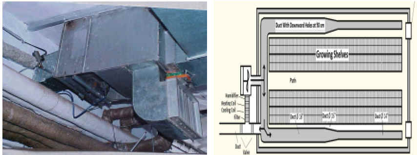
Fig .15. Mdoified
AHU with fresh air fans
Fig.
16. A standard AHU with
centrifugal blower and ducts inside the growing room
from the boiler
to generate required humidity in combination with air pressure or can employ fine jets, which produce fine mist of
water in the humidifier section of the AHU. PVC eliminators, eliminate the free water
going inside the growing room. Booster fan in combination with supply air fan supplies
fresh air inside the AHU through fresh air dampers. Since fresh air coming from outside
atmosphere may contain fungal spores, which may contaminate the crop, this air is
generally passed through pre filters and a HDPE micro filter section (2-5 um). The AHU has a
mixing chamber with recycling dampers, which can regulate supply of fresh air or
room air inside the growing room. Out let of the AHU is connected to the distribution duct
in the growing room, which is generally made up of PVC sheeting having its end month
closed. It hangs below the ceiling in the central corridor of the room. This duct has ports
(5 cm dia) facing downward at a distance of around 50 cm each. When the air is blown inside
the room via AHU a positive pressure is created and CO2 laden air of the growing
room is expelled in the atmosphere through an outlet. In such cases back vents are not
provided in the growing rooms. Alternatively AHU can be so fabricated having provision
to exhaust CO2 laden air of the growing room in the atmosphere through an out let. In
such cases back vents are not provided in the growing rooms Central cooling unit can employ ammonia, freon or vapour
absorption machine (VAM) for cooling purpose. If size and capacity of growing unit
is small, say 250 MT per annum employing around 12 rooms then cooling employing
evaporator, inside the AHU can also be chosen. In such a case each AHU will be a self
contended cooling unit,
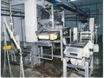
Fig..17. An
automatic canning line
employing, compressor, condenser and an evaporator. This unit will also have heating
and humidifying arrangements.
k. Processing unit
Design of the processing unit with its various components is given in the Fig..17
& 18. Utmost strict hygienic conditions are required to be maintained in the canning
hall and hence special care has to be given at this front while designing/ constructing
canning unit. The floor must be well laid off preferably having kota stone having slope
at one end. Walls should have ceramic tiles up to the height of
5-6 ft. Height of the canning hall should be not less than 14 ft in any case.
Surrounding where this facility is built should be clean and away from the composting yard.
Floor of the canning hall should have enough strength to support
the weight of different utilities to be installed required for the canning
operation. Canning hall should be big enough looking to the future requirements or processing
of other items. All the doors and windows should have wire mesh shutters to prevent the
entry of insects and flies. Three-four exhaust fans should be installed in the hall
at the appropriate places.
Cold room should be properly insulated with minimum of 10 cms
insulating material and separate product cooler of required tonnage should be installed
to it. FPO license is required for processing purpose.

Fig. 18. Design of
a canning unit